MGN 657 (M+F) Amendment 2 Appendix
Published 2 April 2026

© Crown copyright 2026
This publication is licensed under the terms of the Open Government Licence v3.0 except where otherwise stated. To view this licence, visit or write to the Information Policy Team, The National Archives, Kew, London TW9 4DU, or email: psi@nationalarchives.gov.uk.
Where we have identified any third party copyright information you will need to obtain permission from the copyright holders concerned.
This publication is available at /government/publications/mgn-657-mf-amendment-2-requirements-for-fixed-aerosol-fire-extinguishing-systems-for-use-in-small-vessel-machinery-spaces/mgn-657-mf-amendment-2-appendix
APPENDIXÌýMCA Fire Test Approval Procedures -ÌýFixed Aerosol Fire Extinguishing SystemsÌýfor Small Vessel Machinery SpacesÌý
1. DefinitionsÌý
1.1.1 AerosolÌýis a fire-extinguishing medium consisting of finely divided solid particles of chemicals released into a protected space as either condensed aerosolÌý(pyrotechnic charge)Ìýor dispersed aerosolÌý(compressed carrier gas).Ìý
1.1.2 GeneratorÌýis a device for creating aÌýcondensedÌýaerosol fire extinguishing medium by pyrotechnical means.Ìý
1.1.3 Test Density (g/m3)Ìýis the mass of aÌýsolidÌýaerosol forming composition per cubic metre of the enclosure volumeÌýrequiredÌýto extinguish a specific type of fire asÌýdeterminedÌýbyÌýtheÌýtestingÌýregimeÌýdescribed below.Ìý
1.1.4 Design Density (g/m3)Ìýis the mass of aÌýsolidÌýaerosol forming composition per cubic metre of the machinery space onboard provided to extinguish a specific type of fire, which is equal to the test densityÌýincreased byÌýsafety factor of 1.3.Ìý
1.1.5 Medium –ÌýtheÌýaerosol productÌýcontainingÌýboth the active fire suppressant and theÌýby productsÌýof the combustion process which generated the aerosol stream.Ìý
1.1.6 AgentÌý- medium for the purpose of these guidelines, these words are interchangeable.Ìý
1.1.7 ÌýCasingÌý–ÌýTheÌýcasing of the condensed aerosol generator, that is the metal outer part of the generator.ÌýÌý
2. Test EnclosuresÌý
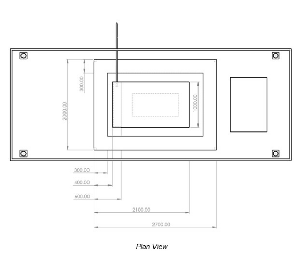
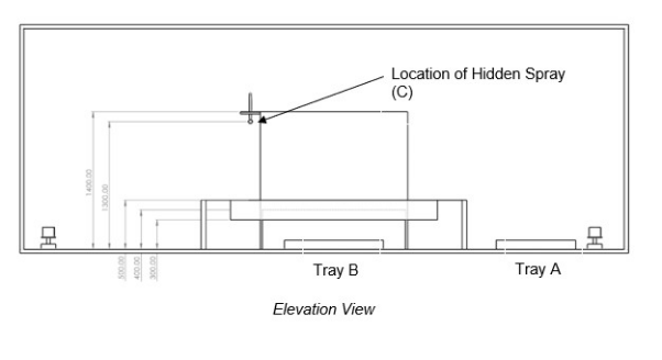
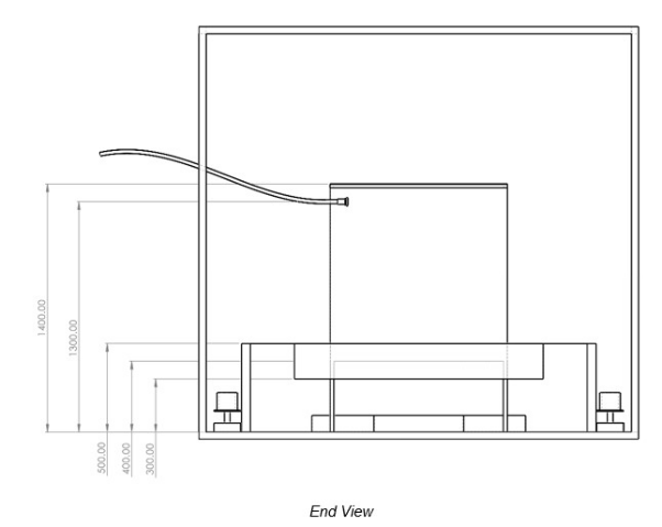
2.1 Figures (1) and (2) are for a small machinery space mock-up, constructed within a 20-foot ISO steel container. The container is oneÌýoption; other enclosures may also be used for the testÌýsubject to approval by the Approved Body and with agreement of the MCA. A mock-up of an engine shall be created in the test enclosure toÌýrepresentÌýthe expected fire scenarios more accurately than for an empty container with no obstructions to the seat of the fire. Figure (2) provides details for this mock up.ÌýÌýÌý
2.2 IMO MSC.1/Circular 1270 “Revised Guidelines for the Approval of Fixed Aerosol Fire-Extinguishing Systems for Machinery Spaces test methodsâ€� is used as the basis for these tests, with a smaller test enclosure volume and fire sizes toÌýmore accurately represent the small machinery spacesÌýbeing approved.Ìý
2.3 The test enclosure volume should be at least equal to that of a standard 20-foot ISO container.ÌýÌý
2.4 Tray A is placed in theÌýenclosure away from obstructions including the mockÌýengine.ÌýA simulatedÌýbilge system is created by plating-in close to the sides of the engineÌýmockup,Ìýwith a fuel tray (Tray B) placed underneath theÌýmock ‘engine’Ìýto simulate fuel accumulationÌýfrom a leak. A fuel-spray is situated at the forward end of the engine mock-up, aiming across the engine and hidden by a plateÌýplacedÌýoverÌýit. Also, in the four corners of the enclosure, small cansÌýwith 0.3 litres of heptaneÌýare placedÌýat floor level in the four corners of the test enclosureÌýto check the distribution of the extinguishing agent.ÌýThe fire in all four cans shall be extinguished.Ìý
2.5 The Wood Crib should be made of kiln spruce and consist of four layers,Ìýeach layer being made up of three members; the size of each member being 38 mm x 38 mm x 260 mm. Ignition of the crib is achieved by burningÌý1.5 litres ofÌýheptaneÌýon a 12.5 litre layer of waterÌýin aÌý500 mm x 500 mm x 100mmÌýsquare panÌýwith steel walls of 6mm thicknessÌýlocated underneath the crib. The bottom of the crib should be 140 mm above the floor. The members should be placed in 4 alternate layers at right angles to one another. Members should be evenly spaced forming a square structure.ÌýThe pre-burn time for the wood cribÌýis 2Ìýminutes.ÌýThe wood crib shall beÌýlocatedÌýbetween trays A and B in Figure 1 below.Ìý
3. Required Fire TestsÌý
3.1 A series of eight tests should be conducted as follows:Ìý
3.1.1 Open poolÌý(Tray A)Ìýfire - diesel fuelÌý(DieselÌýFuel means light diesel or commercial fuel oil).Ìý
3.1.2 Hidden spray fire - diesel fuel.Ìý
3.1.3 Hidden pool fireÌý(Tray B)Ìý- lubricating oilÌý(Lube oil meaning 15W-40 heavy duty diesel engine oil, or similar).Ìý
3.1.4 Combined open poolÌý(Tray A)Ìý/Ìýhidden sprayÌý-ÌýdieselÌýfuel.Ìý
3.1.5 Combined open poolÌý(Tray A)Ìý/Ìýhidden poolÌý(Tray B) -ÌýdieselÌýfuelÌý/Ìýlube oil.Ìý
3.1.6 Combined hidden poolÌý(Tray B)Ìý/Ìýhidden spray - lube oilÌý/ÌýdieselÌýfuel.Ìý
3.1.7 Combined open poolÌý(Tray A)Ìý/Ìýhidden poolÌý(Tray B)Ìý/ hidden sprayÌý/ heptane filled cans -ÌýdieselÌýfuelÌý/Ìýlube oilÌý/ÌýdieselÌýfuel / heptane.Ìý 3.1.8 Wood Crib (Class A fire)Ìý
Note:ÌýÌý3.1.1 toÌý3.1.7 are for Class B fires.ÌýCombined tests can be used toÌývalidateÌýthe effectiveness of single tests at the discretion of the approved body.Ìý
3.2 With reference to the Figures 1 and 2, Tray A shouldÌýcontainÌý10 litres of diesel fuel; Tray B shouldÌýcontainÌý5 litres of lubricating oil and 5 litres of diesel fuel.ÌýWhen required for the relevant fire test,Ìýtrays should have a water base and may be started using heptane as an accelerant.ÌýÌý
3.3 The hidden spray should provide a flow of 1Ìýlitre perÌýminuteatÌý3 bar pressure. The fuel spray should beÌýshut-offÌý15 seconds after extinguishment. At the end of theÌý15 minuteÌýhold-timeÌýafter the end of the aerosol discharge during which the test enclosureÌýremainsÌýclosed, the fuel spray should be restarted for 15 seconds prior to reopening the door and there should be no re-ignition.Ìý
Figure 1: Test enclosureÌý(Plan View all Dimensions inÌýmillimetres)Ìý
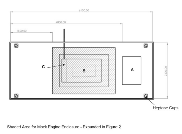
Table 1:Ìý FireÌýscenariosÌý
| Ref. | Constituents | Quantity | Container type | Container size |
|---|---|---|---|---|
| Tray A | Diesel fuel oil | 10ÌýLÌýdiesel fuel | Steel tray | 1.20 m x 0.80 m = 0,96Ìým2 |
| Tray B | Engine lube oil and diesel fuel | 5ÌýLÌýlube oil and 5ÌýLÌýdiesel fuel | Steel tray | 1.00 m x 0.50 m =0.50 m2 |
| Spray C | Hidden spray fireÌý | Ìý | Ìý | Ìý |
| (Diesel fuel oil) | 1ÌýL/min | PressurizedÌýcontainer at 3 bar pressure | - | Ìý |
| Cans 1-4 | Heptane | 0.3ÌýL/can | Open tin approx. 100ÌýmmÌýdiameter | 100 mm internal diameter and 100 m in height |
| Wood Crib | Kiln dried spruce or fir limber members. (Allowable moisture 9 % to13 %) | 12 ofÌý38 x 38 x 260 mm | - | The members are to be placed in 4 alternate layers of three at right angles to one another. Members are to be evenly spaced forming a square structure (spacing approx. 50 mm).ÌýThe wood crib should beÌýlocatedÌýwhere Tray A would be placed. |
Figure 2: Engine mock-up (all Dimensions inÌýmillimetres)Ìý
3.4 A pre-burn time of 2 minutes for the tray fires, and 5 seconds for the spray fire should be allowed before the fire extinguishing system is activated. The doors to the test enclosures should be closed just prior to system release to ensure Oxygen levels are notÌýreduced significantlyÌýpre-test. Times to extinguishment and re-ignition, if any, should be noted, together with other details.ÌýÌý
3.5 A continuous measure at a sampling rate of at least 1ÌýHz should be made from temperature thermocouplesÌýlocatedÌýabove each tray and spray fire. Pressure readings, flow rates and duration of the discharge time should also be recordedÌýwhen dispersed aerosol systems are being tested. The extinguishing system should be installed in the test enclosure according to the manufacturer’s design and installation instructions.ÌýThe thermocouple should beÌýlocatedÌýbetween 30 mm and 100 mm above the fire source.ÌýAdditionalÌýthermocouples should be co-located at each generator unit in the discharge stream atÌýa distance of 100Ìýmm to 300 mm from the generator unit outlet. Measurement devices should be appropriately calibrated to a relevant standard agreed by the approved body with traceability accounted for and recorded.Ìý
3.6 An overall restriction is imposed to the effect that the system is only considered suitable for installation in the machinery spaces of small vessels of less than 24 metre load line length.ÌýThe maximum height of the protected space is 4m and theÌýmaximumÌýfloor area (including any areas covered by permanent installations like engines).Ìý
3.7 Please note that this test method has been agreed by the MCA for UK operation and mayÌýor mayÌýnot be acceptedÌýby other maritime administrations.Ìý
3.8 The test arrangement should be representative of the expected arrangement in a ship’s machinery space, for example the distance between generators and the seat of the fire should be similar.ÌýÌý
3.9 The release of an extinguishing agent may produce significant over or under pressurization in the protected space. Measures to limit the induced pressures to acceptable limits may have to be provided.Ìý
4. Principal RequirementsÌý
4.1 The components to be tested should be supplied by the manufacturer together with design and installation criteria, operational instructions, drawings,Ìýtechnical data, certificate of conformityÌýand manufacturing locationÌýsufficient for the identification of the components.Ìý
4.2 The test procedure is intended for the determination of the effectiveness of different aerosol agent extinguishing systems against Class A fires and Class B sprayÌýandÌýpool fires.Ìý
4.3 For aerosol systems, the discharge time should not exceedÌý60Ìýseconds to achieve 85 % of the design density. Systems may need to discharge in a shorter time for reasons other than for fire-extinguishing performance.ÌýThis can be done by weighing of generator units before and after discharge toÌýdetermineÌýthe quantity of aerosol released and by using the readings from the thermocouples co-located with the generator units toÌýdetermineÌýdischarge start and end times.Ìý
4.4 The quantity of extinguishing agent for the protected space should be calculated at the minimum expected ambient temperature using the design density based on the net volume of the protected space.Ìý
4.5 TheÌýgrossÌývolume of a protected space isÌýcalculated from the dimensions of the space.ÌýÌý
4.6 TheÌýnetÌývolume of the spaceÌýisÌýdeterminedÌýby removing the volume of the machinery in the space from the gross volume.ÌýThe objects that occupy volume in the protected space include, but are not necessarily limited to auxiliary machinery, boilers, condensers, evaporators, main engines, reduction gears,ÌýtanksÌýand enclosed trunks.Ìý
4.7 When calculating the net volume of a protected space, the volumes of theÌýbilges,Ìýor the fire extinguishing systemÌýitself should not be removed from the gross volume.ÌýÌý
4.8 The volume of free air contained in air receivers thatÌýin the event ofÌýa fire may be released into the protected spaceÌýalso has to be considered and will add to the net volume.Ìý
4.8.1 The volume of air in air receivers is the volume of air that would be releasedÌýin the event ofÌýa fire to the protected space ambient pressure and temperature. For example, aÌý10 litreÌýair receiver at 10 bar pressure would have an equivalent volume of 100 litres when released to the protected space which is at a nominal 1 bar pressure.Ìý
4.9 SubsequentÌýmodifications to the protected space that alter the net volume of the space should require the quantity of extinguishing agent to be adjusted to meet the requirements.Ìý
4.10 No fire suppression system should be used which is carcinogenic,ÌýmutagenicÌýor teratogenic at concentrations expected during use. The discharge of aerosol systems to extinguish a fire could create a hazard to personnel from the natural form of the aerosol, or from certain products of aerosol generation (including combustion products and trace gases from condensed aerosols). Other potential hazards that should be considered for individual systems are the following: noise from discharge, turbulence, cold temperature of vaporizing liquid, reduced visibility, potential toxicity, thermal hazard and potential toxicity from the aerosol generators, and eye irritation from direct contact with aerosol particles. Unnecessary exposure to aerosol media, even at concentrations below an adverse effect level, and to their decomposition products should be avoided. All aerosols used in fire-extinguishing systems should have non-ozone depleting characteristics.Ìý
4.11 All systems should employ two separate controlÌýactionsÌýfor releasing the extinguishing medium into a protected space, such as lift cover andÌýturn keyÌýor similar. Means should be provided for automatically giving audible warning of the release of fire-extinguishing medium into any space in which personnel normally work or to which they have access. The alarm shouldÌýoperateÌýfor a suitable period, (at least 20 seconds)Ìýbefore the medium is released. Exposure to aerosol media, even at concentrations below an adverse effect level, should be avoided, proper the use of the isolation switch will avoid inadvertent exposures.Ìý
4.12 FixedÌýaerosolÌýfireÌýextinguishingÌýsystemsÌýare onlyÌýfor use inÌýnot normally occupied spaces.ÌýHowever, IMO circularÌý1270 “Revised Guidelines for the Approval of Fixed Aerosol Fire-Extinguishing Systems Equivalent to Fixed Gas Fire-Extinguishing Systems, asÌýreferred to in SOLAS 74, for Machinery Spacesâ€� (4 June 2008) contains further requirements forÌýnormally occupied spacesÌýrelated to theÌýNo Observable Adverse Effect Levels (NOAEL)Ìýfor aerosol systems and their by-products (such as Carbon Monoxide). Compliance with these requirements does not need to beÌýdemonstratedÌýfor systems to be used inÌýnot normally occupied spaces,Ìýhowever as the spaces are occasionally occupied, the MCA will review manufacturer’s evidence of aerosol and by-products toxicity before approving any systems for use inÌýnot normally occupied spaces.Ìý
4.13 In no case should a dispersed aerosol system be used with halocarbon carrier gas concentrations above the “Lowest Observed Adverse Effect Level (LOAEL) nor the “Approximate Lethal Concentration (ALC)â€�.Ìý Nor should a dispersed aerosol system be used with an inert gas carrier at gas concentrations above 52 %Ìýcalculated on the net volume of the protected space at the maximum expected ambient temperature, without the use of controls.Ìý
4.14 The system and its components should be suitably designed to withstand ambient temperature changes, vibration, humidity, shock, impact, clogging, electromagneticÌýcompatibilityÌýand corrosion normallyÌýencounteredÌýin machinery spaces. Generators in condensed aerosol systems should be designed to prevent self-activation at a temperature below 250 °C.ÌýThis can beÌýdemonstratedÌýthrough existing test reports or through new testing to the satisfaction of the approved body.Ìý
4.15 The system and its components should be designed,ÌýmanufacturedÌýand installedÌýin accordance withÌýstandards acceptable to the International Maritime Organisation (IMO) and the National Authority (MCA). As a minimum, the design and installation standards should cover the following elements:Ìý
4.15.1 Safety:
-
Toxicity.Ìý
-
Noise - Generator/Nozzle discharge.Ìý
-
Decomposition products.Ìý
-
Obscuration.Ìý
4.15.2 Storage container design and arrangement strength requirements:Ìý
-
MaximumÌý/ÌýminimumÌýfill density,Ìýoperating, temperature range.Ìý
-
Pressure & weightÌýindication.Ìý
-
Pressure relief.Ìý
-
Agent identification, production date, installation date & hazard classification.Ìý
4.15.3 Agent supply, quantity, quality standards, shelf life & serviceÌýlife of an agent and igniter.Ìý
4.15.4 Handling & disposal of generator after service life.Ìý
4.15.5 Pipes and fittings:Ìý
- Strength, material properties, fireÌýresistanceÌýand cleaning requirements.Ìý
4.15.6 Valves: Ìý
-
Testing requirements; andÌý
-
Elastomer compatibility.Ìý
4.15.7 Generators/Nozzles:Ìý
-
Height & testing requirements; andÌý
-
Elevated temperature resistance.Ìý
4.15.8 Actuation & Control Systems:Ìý
-
Testing requirements; andÌý
-
Backup power requirements.Ìý
4.15.9 Alarms & Indicators:Ìý
-
Predischarge alarm, agent discharge alarms & time delays.Ìý
-
Supervisory Circuit requirements.Ìý
-
Warning signs, audible & visual alarms.Ìý
-
Annunciation of faults (fault warning).Ìý
4.15.10 Enclosure integrity & leakage requirements:Ìý
-
Enclosure leakage.Ìý
-
Openings.Ìý
-
Mechanical ventilation interlocks.Ìý
4.15.11 DesignÌýand testÌýdensity requirements, total flooding quantity.Ìý
4.15.12 Agent flow calculation:Ìý
-
Verification & approval of design calculation method.Ìý
-
Fitting losses and/or equivalent length.Ìý
4.15.13 Inspection, maintenance,ÌýserviceÌýand testing requirements.Ìý
4.15.14 Handling & storage requirements for pyrotechnical components.Ìý
4.16 Agent containers may be stored within a protected machinery space if the containers are distributed throughout the space. The arrangements of generators, containers, electrical circuits & piping essential for the release of any system should be such that in the event of damage to any one power release line through fire or explosion in the protected space (i.e. a single fault concept), at least theÌýtestÌýdensity of the fire-extinguishing charge as required in paragraphÌý4.15.11 above can still be discharged having regard to the requirement for uniform distribution of medium throughout the space.Ìý
4.17 For all ships, the fire-extinguishing system design manual should address recommended procedures for the control of products of agent decomposition. The decomposition products should not be discharged in the vicinity of assembly spaces.Ìý
4.18 Spare parts andÌýoperatingÌý& maintenance instructions for the system should be provided as recommended by the manufacturer.Ìý
5. Success Criteria:ÌýÌý
5.1    Class B fires should be extinguished within 30 s of the end of discharge. At the end of the hold period there should be no re-ignition upon opening the enclosure.Ìý
5.2   The fuel spray should be shut off 15 s after extinguishments. At the end of the hold time, the fuel spray should be restarted for 15 s prior to reopening the door and there should be no re-ignition.Ìý
5.3   The ends of the test fuel trays shouldÌýcontainÌýsufficient fuel to cover the bottom of the tray.Ìý
5.4   The wood crib weight loss should be no more than 30% during the 2 min pre-burn test.Ìý
5.5    A re-ignition test should be conducted after the successful extinguishments of the tell-tale fires in test 1 (Fire A) within 30 s after completion of discharge. The test should involve the attempted ignition of two of the tell-tale fire containers. One container should be at the floor level and the other at the ceiling level at the diagonally opposite corner. At 10 min after extinguishment of the fires, a remotelyÌýoperatedÌýelectrical ignition source should be energized for at least 10 s at each container. The test should be repeated at 2 min intervals two more times, the last at 14 min after extinguishment. Sustained burning for 30 s or longer of any of these ignition attempts constitutes a re-ignition test failure.Ìý
6. Test Report:ÌýÌý
6.1 The test report should include the following information:Ìý
6.1.1 Name and Address of the Test Laboratory.Ìý
6.1.2 Date and Identification Number of the Test Report.Ìý
6.1.3 Name and Address of Client.Ìý
6.1.4 Purpose of the Test.Ìý
6.1.5 Method of Sampling System Components.Ìý
6.1.6 Name and Address of Manufacturer or Supplier of the Product.Ìý
6.1.7 Name or other Identification Marks of the ProductÌý(for example serial numbers, date of manufacture, expiry date etc.).Ìý
6.1.8 Description of the Tested Product:Ìý
6.1.8.1 Drawings.Ìý
6.1.8.2 Descriptions.Ìý
6.1.8.3 Assembly Instructions.Ìý
6.1.8.4 Specification of included Materials.Ìý
6.1.8.5 Detailed Drawing of Test Set-up.Ìý
6.1.9 Date of Supply of the Product.Ìý
6.1.10 Date of Test.Ìý
6.1.11 Test method.Ìý
6.1.12 Drawing of each test configuration.Ìý
6.1.13 Identification of the Test Equipment and Instruments used.Ìý
6.1.14 Conclusions.Ìý
6.1.15 Deviations from the Test Method, if any.Ìý
6.1.16 Test Results including measurements and observations during and after the test.Ìý
6.1.17 Date, Name and Signature of qualified personÌýwitnessingÌýthe test.Ìý
7. Certificate:ÌýÌý
7.1 On successful completion of the eight tests mentioned in paragraph 1.6 a Certificate of Inspection and Tests will be issued and the Aerosol systemÌý/Ìýproduct will be considered suitable for installation in normally unoccupied spaces containing fuel having a flash point of not less than 43Ìý°C (closed cup test), of vessels of less than 24 metres load line length, where the space to be protected does not exceed a deck height of 4 metres, orÌýdeckÌýarea greater than 64 square metresÌýequal to 256 m3, this volume is the maximum permitted volume for approvals under this MGN.ÌýThe certificate willÌýstateÌýthat the system/product is acceptable for the purpose ofÌýcomplying withÌýthe requirements of:Ìý
7.1.1 MGN 280 - Small Vessels in Commercial Use for Sport or Pleasure, Workboats and Pilot Boats - Alternative Construction Standards.ÌýAs Amended.Ìý
7.1.2 The Codes of Practice for the Safety of Small Commercial Motor or Sailing Vessels of up to 24 metres Load Line length.ÌýAs amended.Ìý
7.1.3 “The Safety of Small Workboats and Pilot BoatsÌý-ÌýA Code of Practice. As amended.ÌýÌý
7.1.4 MSN 1871 (F) The Code of Practice for the Safety of Small Fishing Vessels of less than 15m Length Overall.ÌýAs amended.Ìý
7.1.5 MSN 1872 The Code of Safe Working Practice for the construction and use of fishing vessels of 15m length overall to less than 24m registered length.ÌýAs amendedÌý
7.1.6 The Codes of Practice for Police Boats.ÌýAs amended.ÌýÌý
7.1.7 ÌýNon-Category A Machinery Spaces in domestic passenger ships of Class III to VI(A) where theÌýrequirementÌýwasÌýintroduced by the Merchant Shipping (SafetyÌýStandards for Passenger Ships on Domestic Voyages) (Miscellaneous amendments) Regulations 2022.Ìý
8. References:Ìý
(a) International Maritime OrganizationÌýÌý MSC.1/Circ.1270ÌýofÌý4 June 2008Ìý
“Revised Guidelines for the Approval of Fixed Aerosol Fire Extinguishing Systems Equivalent to Fixed Gas Fire Extinguishing Systems, as referred to in SOLAS 74, for Machinery Spaces.Ìý
(b) International Maritime Organization MSC/Circ. 668 of 30 December 1994 “Alternative arrangements for Halon Fire Extinguishing Systems in Machinery Spaces and Pump Roomsâ€�.Ìý
(c) IMO 2010 FTP Code. International Code for Application of Fire Test Procedures, 2010 ISBNÌý 978 92 801 1548 2 (International Maritime Organization).